The F-150 is finally off jack-stands. 6 weeks ago they went under and an additional two weeks more since it had actually been driven - the pollen accumulation on Allie’s CX5 can attest to this as the truck sat squarely in the middle of the garage. Once again I prove that without a proper forcing function I take my time with projects. My artificial due dates are powerless.
I’ve put together a how-to guide complete with pictures and all the fun things I encountered along the way.
What is it?
Geometry this geometry that
Just read the wikipedia on control arms if you’re really interested.
It serves as the upper connecting piece between the vehicle’s frame and the steering knuckle, mostly responsible for guiding the up-and-down movement and maintaining the camber of the wheel (how far in/out the tire is leaning).
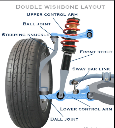
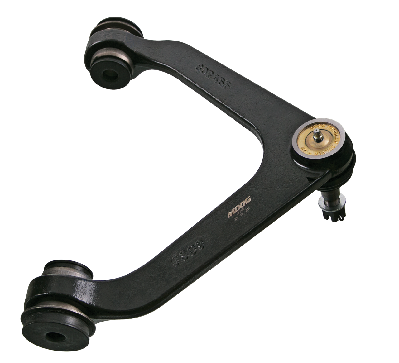
They’re typically ‘V’ shaped where the feet of the ‘V’ contain big fat bushings that connect to the vehicle frame while the point contains a ball joint that slides through the knuckle.
Why are you doing this?
Philosophically or physically?
Remember how I said it aids in the control of camber and therefore how much tire is actually contacting the road? Well the insides of both my front tires were balding…the ball joints had resigned to their fates of dancing about due to age - 23 years of wear and tear will do that! Not to mention, every time I hit an incline (say every parking lot I entered down here in League City) my whole frontend would groan and clunk.
Worn upper ball joints → sloppy camber control → wheel tilts unpredictably as suspension moves → tire doesn’t stay flat on road → uneven wear → scary tire situation
It may or not be obvious but, the clunking itself wasn’t the reason I decided to swap them out. “Vehicles are only as safe as its tires allow it to be” - another bit of wisdom I imagine my Dad told me long ago that didn’t quite solidify until I was sliding around on the roads to ski resorts.
In fact, I sort of liked hearing it for reasons that are still unclear to me - perhaps something to do with the truck having character or some brewing excitement that there was another excuse to buy more tools (I knew this meant I was going to need a big-ahh torque wrench).
How-to Guide
Yes, this is professional advice
It should be pretty much the same for every vehicle that has wishbone suspension - newer cars are going to have a lot more things to disconnect and work around so 🐝 careful…
Initial Prep
A proper ritual
First things first, we need to get the vehicle up on jack stands and the wheels off. I always loosen the lug nuts on the wheels prior to jacking it up for the sake it being a bit safer and much easier. Trying to take lug nuts off an airborne wheel just makes it spin and increases the risk of it just falling off the stand.
Often times when people are working on front suspension components, they jack it up from the front of the vehicle since they’re usually working symmetrically. I simply didn’t have space in my garage to do that so I did it one side at a time. Once you’ve got the wheel completely off the ground, throw a stand or two under there and slowly lower the weight of the vehicle on it then give the jack another pump for the sake of an additional contact point.
Now remove the wheel and throw it under the vehicle too. Throw on the emergency brake and chock the back wheels if you really feel like it. Can never be too cautious when working with a multi-ton piece of machinery.
Remove the cotter pin from the castle nut that connects the arm to the knuckle. It’s easier said than done, it took me longer than I care to admit to wiggle it free. There may also be a little clip for the brake line that wraps around the arm that’ll need removing too.
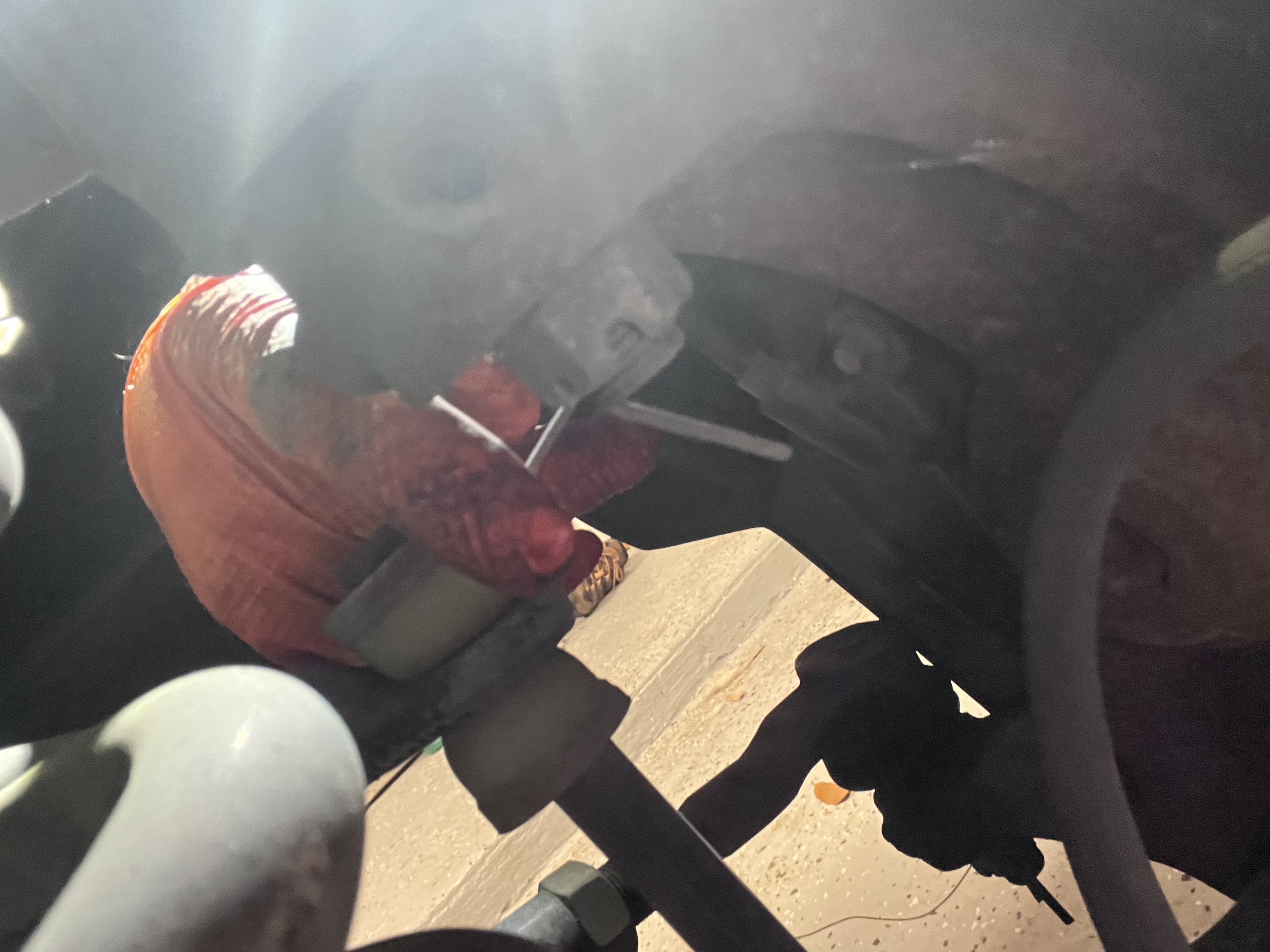
Loosen the castle nut but not all of the way, just enough such that all threads of the nut are still engaged on the bolt that way the arm won’t coming flying out when we start beating the knuckle with a hammer.
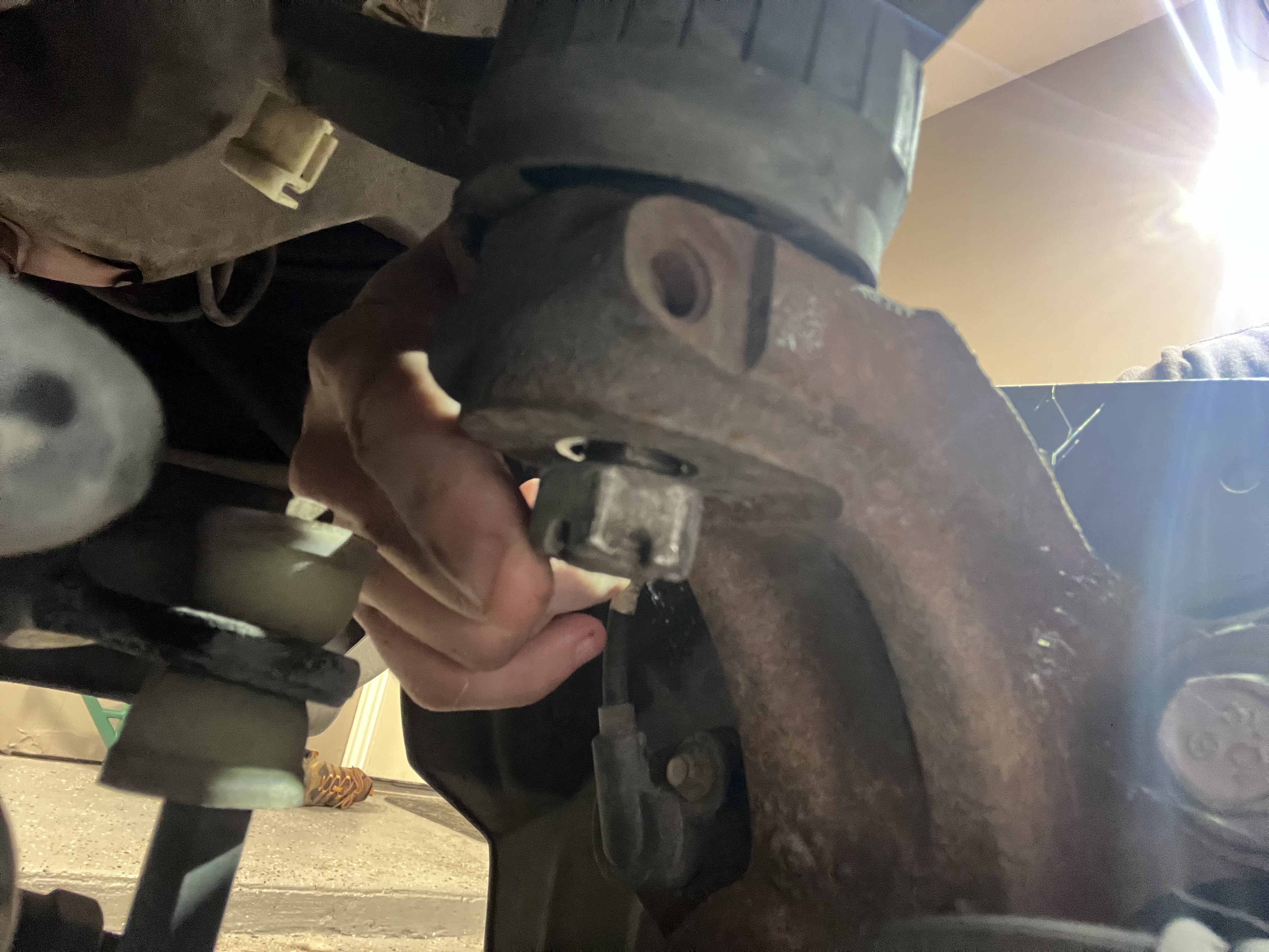
Yes, we need to beat it with a hammer in order to loosen the ball joint. I obviously approached this with a limp wrist as I really didn’t want to break anything. But after quite a bit of smashing with a rubber mallet to no avail, I swapped to a metal one and had to really lay into it. A dozen or so swings later the connecting piece loosened with a thunk as the castle nut caught it and kept the knuckle from slamming to the ground.
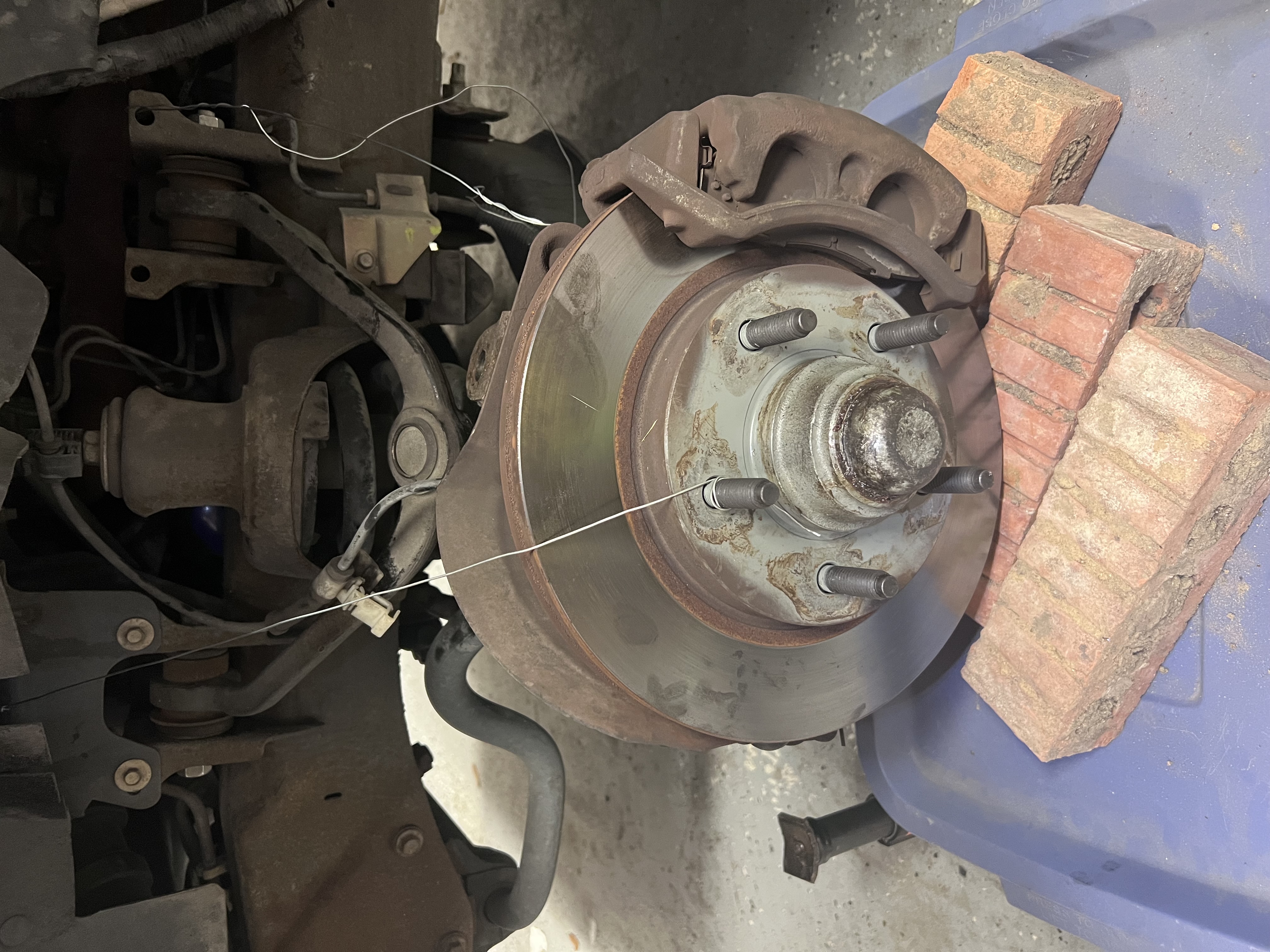
Knuckle Support System
Even knuckles need one
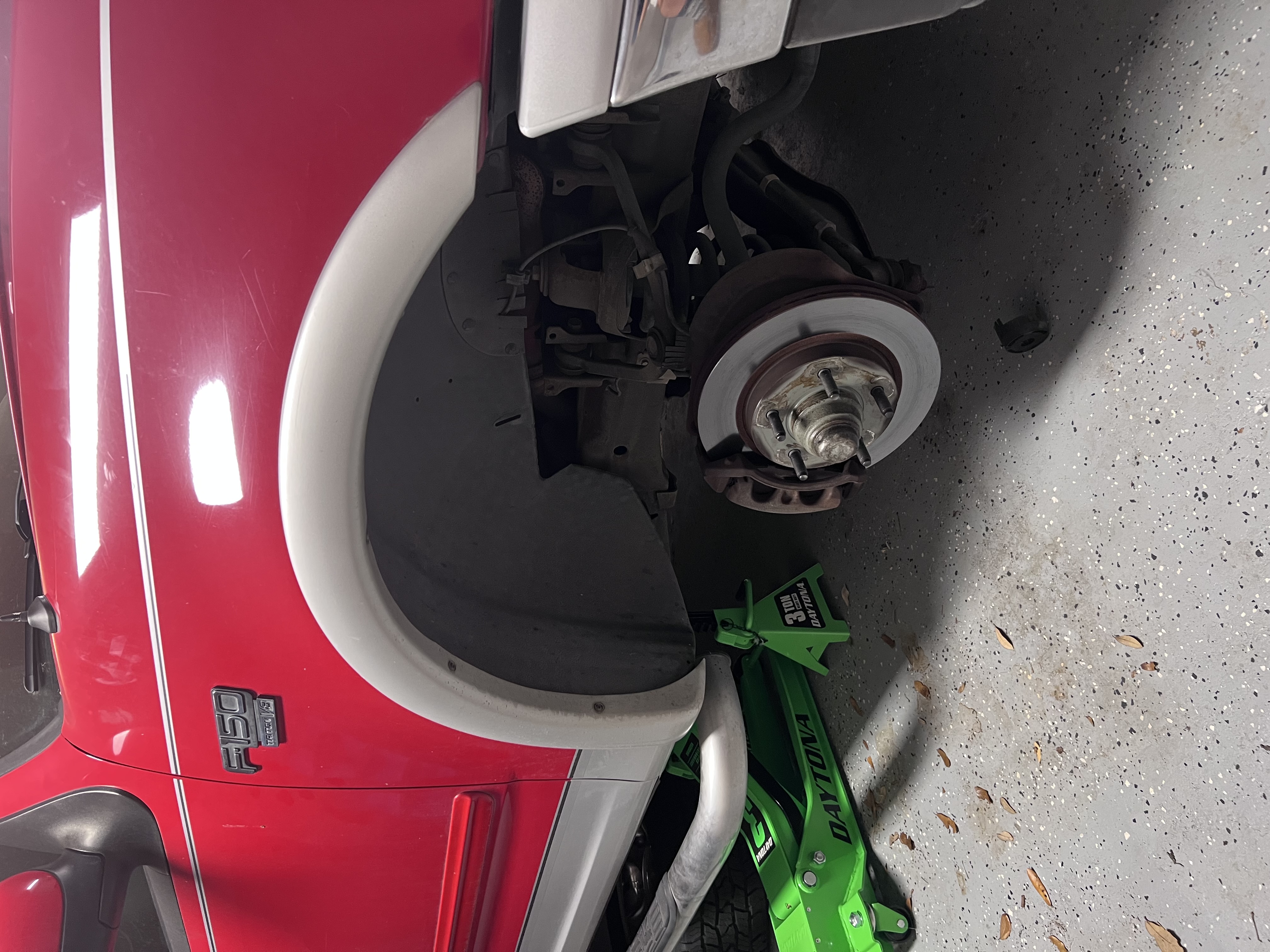
With the upper control arm removed, the knuckle just wants to go all over the place and can mess up your rotors and disconnect brake lines and all sorts bad things. To prevent that, you’ll need a way to secure it. My plan involved a collection of mechanic wire and a storage bin with some bricks stacked on top to get a “stable” platform lol
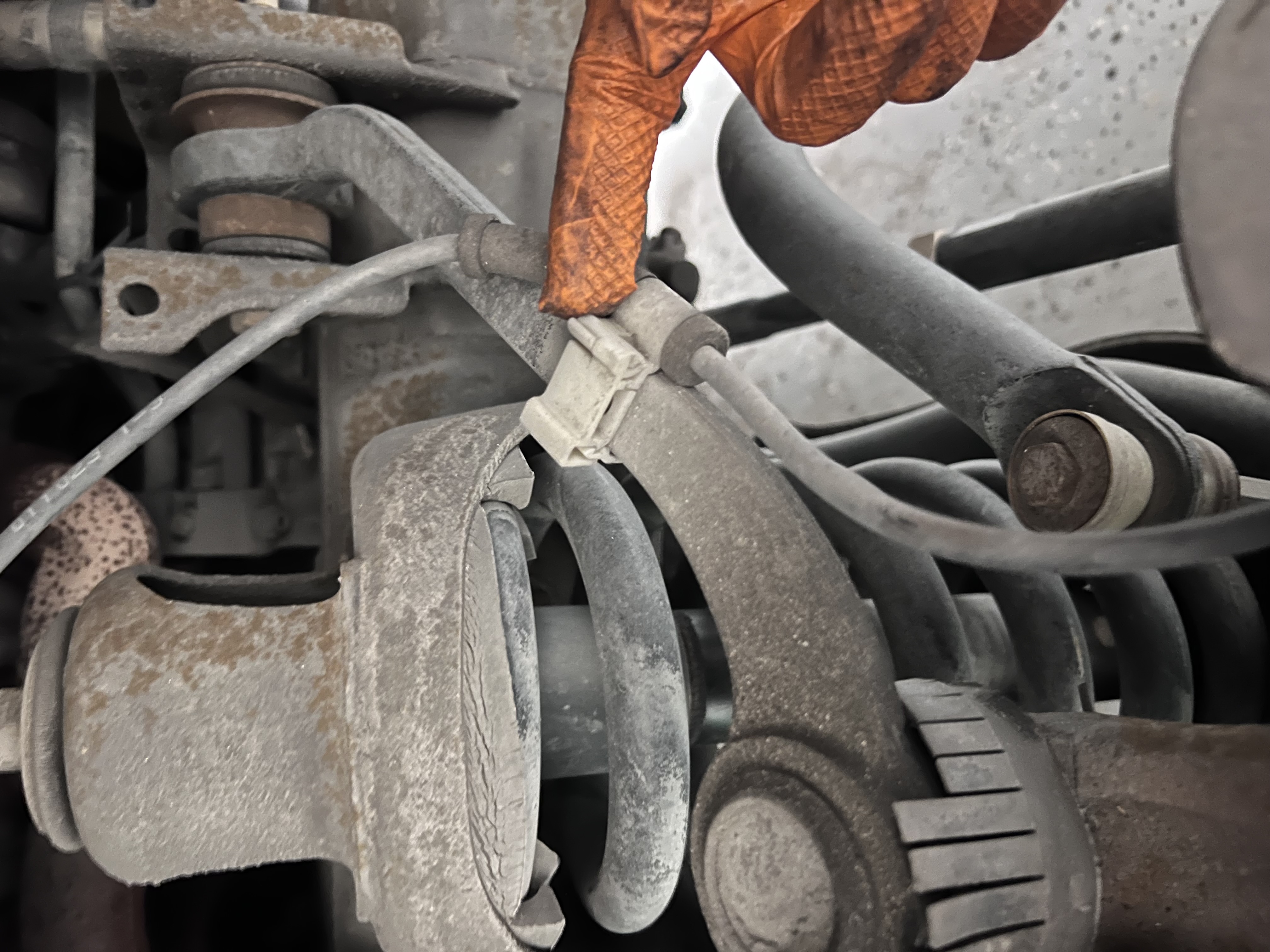
At this point you should loosen the bolts connecting the arm to the frame. This will begin our journey of using two socket wrenches. Hold the inside bolt head steady with one socket, and loosen the nut on the outside, otherwise it’ll just spin indefinitely.
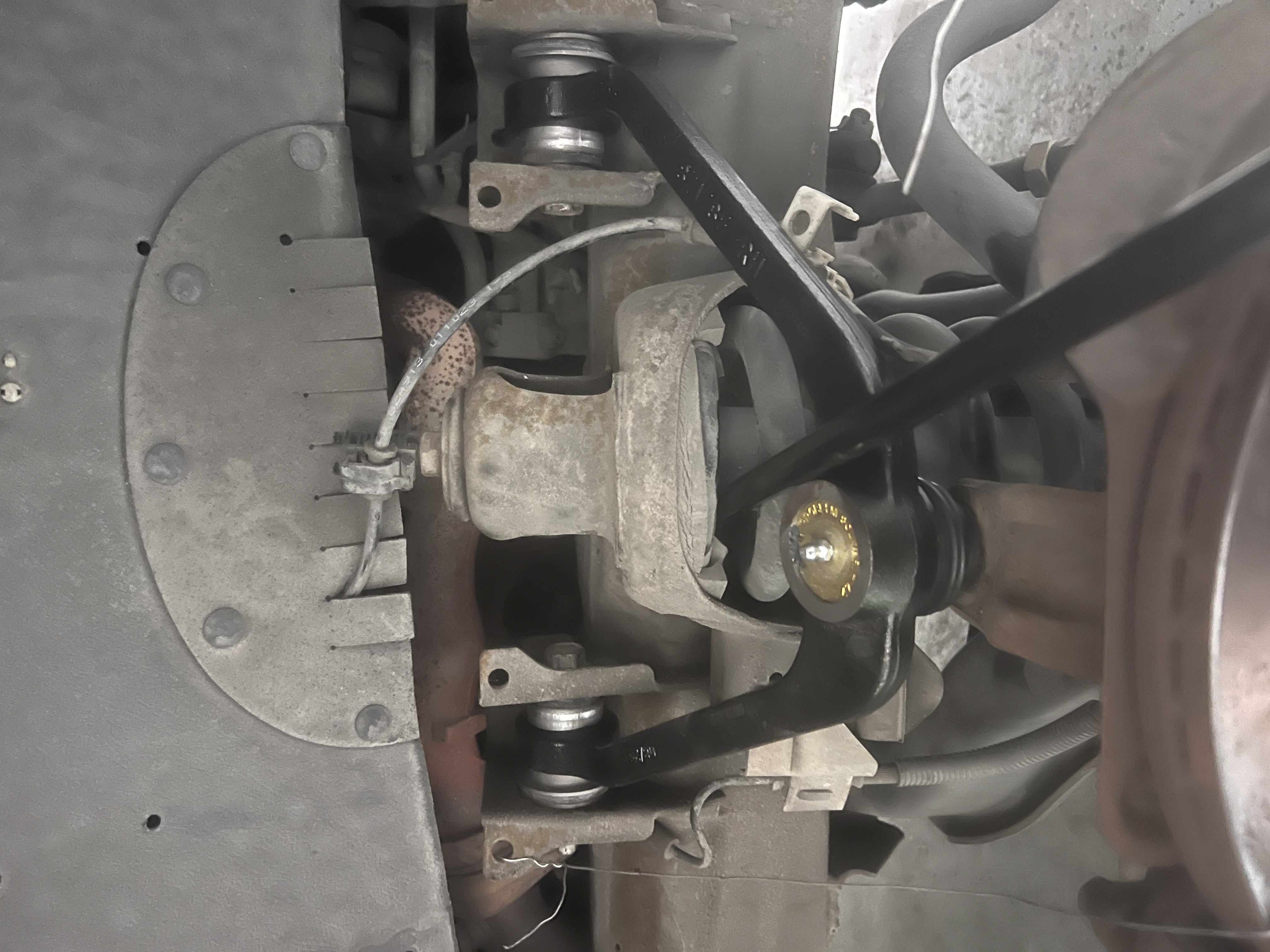
After loosening the frame connection and you’re confident nothing will go flying, remove the castle nut while applying pressure to the arm using a pry-bar wedged into something on the vehicle (I used my springs) and slowly relieve pressure as you try and wiggle the ball joint bolt out of the knuckle.
I didn’t snag a closeup picture of the bolts, but you can see them pretty clearly on the left and right sides of the “V”.
The Swap
Out with the old in with the slightly stiffer
Remove the bolts from the frame connection and rip that arm out. It’ll take some finesse and lots of wiggling (you will not cause the vehicle to fall off the stands don’t worry). Once removed, set it aside and play with the ball joint and realize just how horribly wiggly it is. Nothing that wiggly should be apart of a suspension system.
Now, admire your new control arm with its glorious lack of wiggle. Once admiration is complete, place the new arm in. It’ll take some finesse and lots of wiggling (you will not cause the vehicle to fall off the stands…are you still worried about this?). Replace the bolts and continue our dual wielding socket saga. When tightening, try to keep the arm at ride-height which can be approximated as simply level. Real ride-height is probably not perfectly level, but this puts much less strain on the bushings then if we were to simply let it hang while torquing it down. Bushings twist, not slide. If you torque them while the arm’s hanging at full droop, then drop the vehicle back to ride height, they’re stuck in a twisted preload and will eat themselves alive. Approximation is your friend here.
Grab that pry-bar from earlier and pull your new arm down through the knuckle, you’ll likely need to use your other hand to help align the hole. The knuckle likely drifted left or right prior to settling on its support system. It’ll take a bit more force than you think, the ball joint of the new arm is VERY stiff. Screw back on the castle nut and torque it down to spec, make sure the cotter pin hole is aligned with an opening on the nut it may take an additional 1/4 turn to get it aligned. Make sure to bend the cotter pin after sliding it through.
Congrats
We ride again
The swap has been completed! Remove your knuckle’s support system and clip back on the brake line to the arm if you can - I had to tie it down with some of that extra mechanic’s wire since the new arm was much thicker than the older one. Get that wheel back on and tighten it enough to where it won’t go falling off. Lower the vehicle, and torque down those lug nuts to spec (star pattern of course).
Now do it on the other side.
Unless you forgot to disconnect the battery and your vehicle sat for two months and the battery is completely dead, you should be good to go get an alignment and be on your way.
Appendix
Parts Purchased and Tools Required
| Item | Notes |
|---|---|
| MOOG Control Arm and Ball Joint Assembly | Driver + Passenger side: https://tinyurl.com/moog-control-arms |
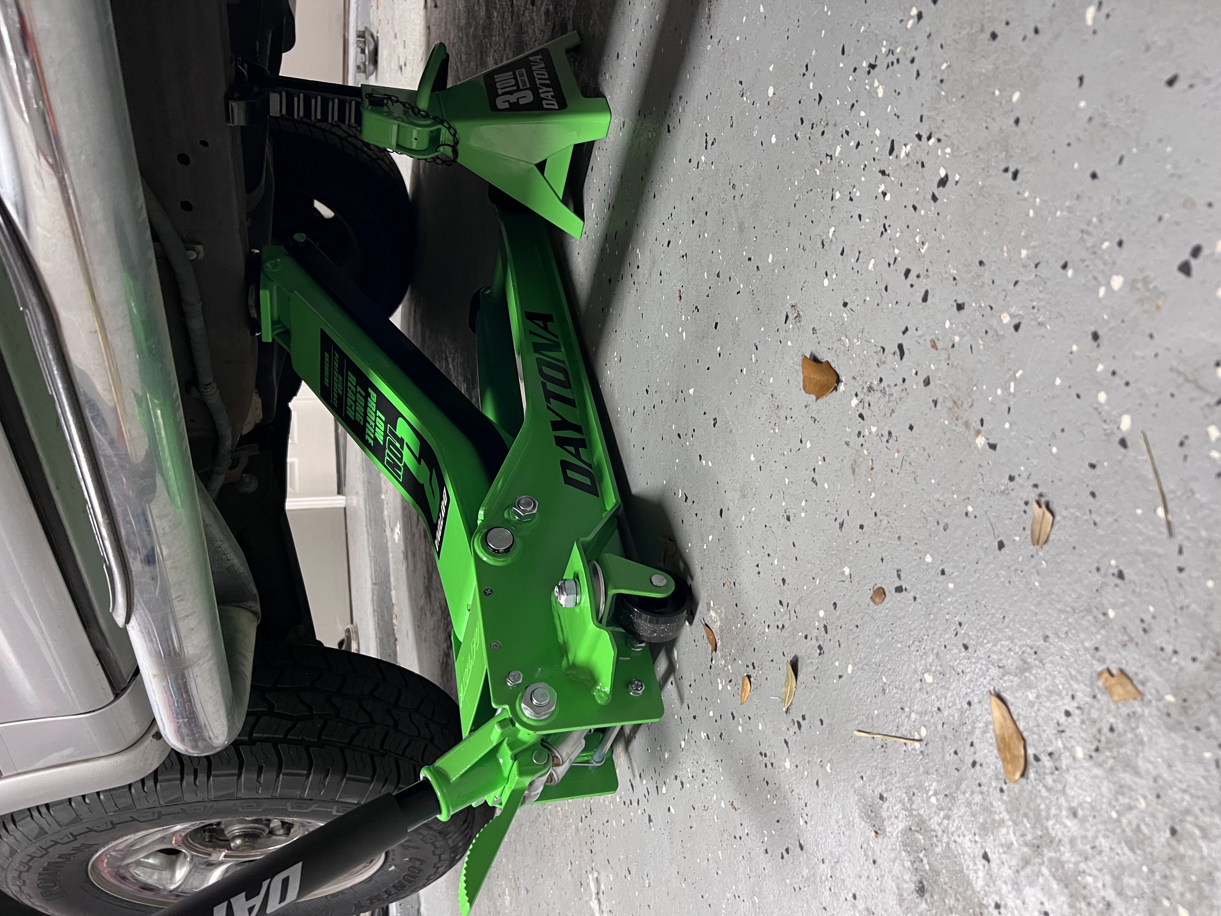
| Daytona 3-Ton Low-Profile Jack | https://tinyurl.com/daytona-low-profile-jack |
| Daytona Jackstands | I’ve got 4 but that’s unnecessary https://tinyurl.com/Daytona-stands |
| Socket Wrench and Socket Set | Need two wrenches - and 20mm and 21mm sockets |
| Pliers | Bending and sliding the cotter pin |
| Hammer | For beating |
| Mechanic’s Wire | Knuckle support system and securing brake line |
| Torque Wrench | ”That ain’t going nowhere” |
Torque Spec’s
| Item | Torque (ft-lbs) |
|---|---|
| Frame Bolts | 100 |
| Castle Nut | 76 |
| Lug-nuts | 150 |